Structured Cabling System Basics
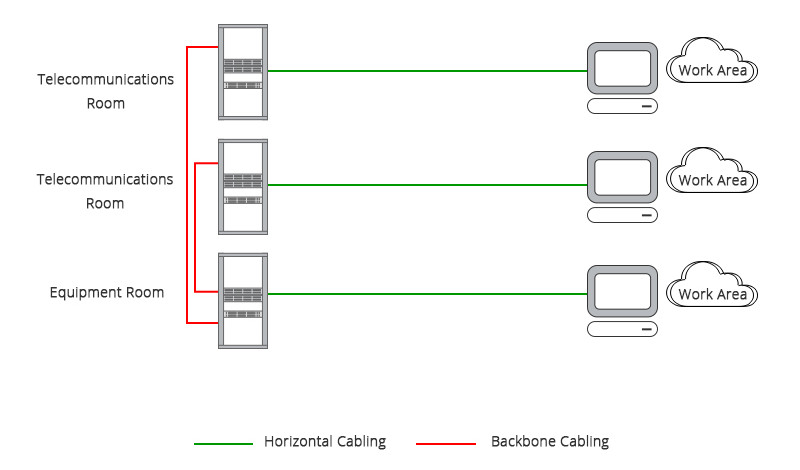
To understand backbone cabling and horizontal cabling, let’s understand the five subsystems of structured cabling firstly. These five subsystems are often found throughout a building and are connected together so that various types of data can be transmitted consistently and securely (shown in the figure below).

Equipment Room: A room with equipment that serves the users inside the building.Telecommunications Room: This room contains the telecommunications equipment that connects the backbone and horizontal cabling subsystems.Backbone Cabling: A system of cabling that connects the equipment rooms and telecommunications rooms.Horizontal Cabling: The system of cabling that connects telecommunications rooms to individual outlets or work areas on the floor.Work Area Components: These connect end-user equipment to outlets of the horizontal cabling system.
Backbone Cabling
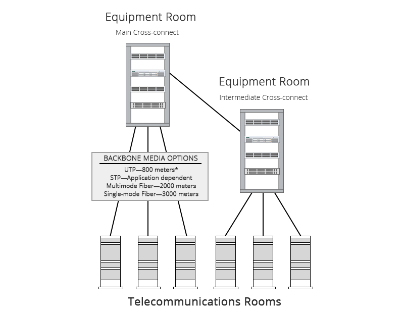
The backbone cabling is also called vertical cabling or wiring. It provides interconnection between telecommunication rooms, equipment rooms and entrance facilities. These backbone cablings typically are done from floor to floor to floor. When setting up backbone cabling, several types of media can be used: unshielded twisted-pair (UTP) cable, shielded twisted-pair (STP) cable, fiber optic cable, or coaxial cable. Equipment should be connected by cables of no more than 30 meters (98 feet).

Cables for Backbone Cabling
With the emerge of Gigabit Ethernet and 10 Gigabit Ethernet, fiber optic cable is the most appropriate choice for backbone cabling since they provide much higher bandwidth than traditional Cat5, Cat6 or even Cat7 twisted pair copper cables. Another advantage of fiber is that fibers can run much longer distance than copper cable, which makes them especially attractive for backbone cabling.
Horizontal Cabling
The horizontal cabling system extends from the work area’s telecommunications information outlet to the telecommunications room (TR) or telecommunications enclosure (TE). As shown in the figure below, horizontal cabling is usually installed in a star topology that connects each work area to the telecommunications room. It includes the telecommunications outlet, an optional consolidation point, horizontal cable, mechanical terminations and patch cords (or jumpers) located in the TR or TE.

Cables for Horizontal Cabling
Both Ethernet cable and fiber optic cable can be used for horizontal cabling. Four-pair 100-ohm unshielded twisted-pair (UTP) cable (Cat5e cable, Cat 6 cable or Cat6a cable) is usually recommended for voice and fiber optic cable (two-fiber 62.5/125-micron or 50/125-micron multimode cable, or higher fiber count ) is commonly used for data transmission. To comply with EIA/TIA wiring standards, individual cables should be limited to 90 meters in length between the outlet in the work area and the patch panels in the telecommunications room. Patch cords for connecting the patch panel to hubs and switches in the telecommunications room should be no longer than 6 meters total distance. Cables connecting users’ computers to outlets should be limited to 3 meters in length.
 汉信
汉信

